

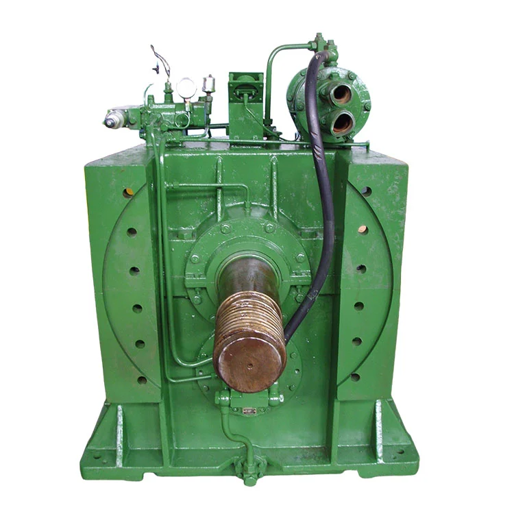
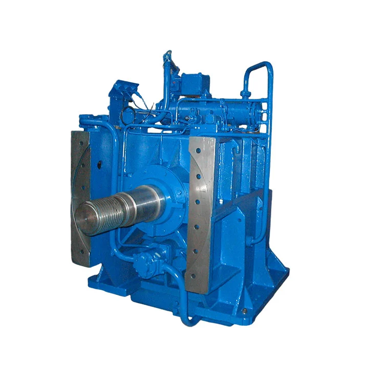
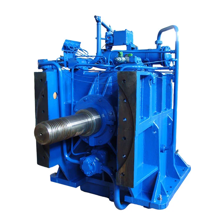
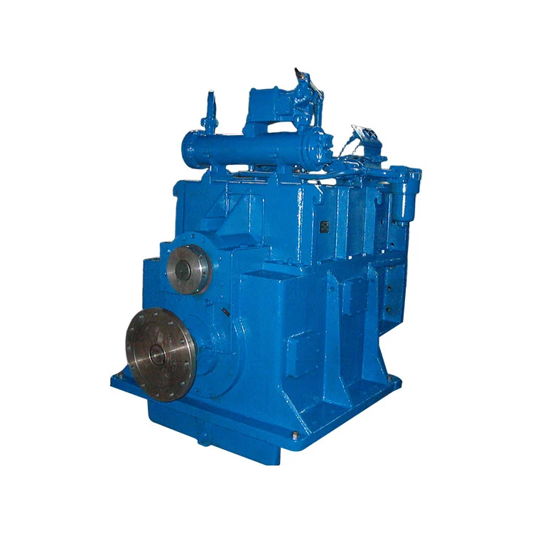
1. This product is a dredger gearbox special for slurry pump, which is designed and manufactured by the mean that combines technology introduced from Germany and current advanced technology in our company. Therefore, the series gearbox is perfect in performance, reliable in operation and convenient in maintenance.
2. Our gearbox is designed with an integral housing, which may also be used as the frame. So it features in perfect rigidity and compact structure. Compared to a slurry pump system applying pneumatic-tube clutch, this system has the advantages of shorter axial length and more economic.
3. Thrust bearings with large capacity are used to bear greater pulling force from slurry pump impeller.
4. It applies tube-type hydraulic system, which is convenient in maintenance. And the high-pressure oil line uses hose to decrease noise in gearbox operation a lot.
Provided that the dredger gearbox is to be operated and maintained correctly according the Manual, it will work reliably for a pretty long term. If any special demands, please contact the designer directly.
| 1. | Matching ship type: | Dredgers of all kinds (also for slurry transportation on-land) |
| 2. | Transmission mode: | Helical cylindrical gear, two shafts and two gears |
| 3. | Clutch type: | Hydraulic, wet, multi-plate frictional clutch |
| 4. | Center distance: | 360mm |
| 5. | Ratio: | 2.2~4 (may be determined on actual request) |
| 6. | Input power: | 1060kW (power and speed may be determined depending on actual situations) |
| 7. | Input speed: | 1300~1800 rpm |
| 8. | Rated trans. torque | 0.7 kW/rpm |
| 9. | Rated thrust from impeller: | 15T |
| 10. | Rotation direction: |
Input end (facing input shaft): clockwise Output end (facing output shaft): clockwise |
| 11. | Mechanical efficiency: | ≥98% |
| 12. | Engagement time: | 2s – 6s |
| 13.1 | Working oil pressure: | 1.5 – 1.63 MPa |
| 13.2 |
Lub. oil pressure at normal speed: at idling speed: |
0.2 – 0.4 MPa ≥0.05 MPa |
| 14. | Oil brand: | HC-11, HQ-10, or SAE30 (free from EP addictive) |
| 15. | Oil capacity: | ~ L |
| 16. | Lub. oil temperature: | 40 –60℃ |
| 17. | Max. oil temperature: | ≤80℃ |
| 18. | Consumption of cooling water: | ≥5 t/h |
| 19. | Cooling water temperature: | ≤32℃ |
| 20. | Engagement speed | ≤60% of rated engine speed |
1. General
This dredger gearbox system is a single-stage reduction box for slurry pump, with input and output shafts vertically arranged. Since the mechanism is special designed to drive slurry pump, the slurry pump case is connected to gearbox housing with bolts and slurry pump rotor directly mounted on the output driving shaft. The gearbox is suitable for not only all kinds of dredgers, but also slurry transportation overland and directly driving water pump.
2. Structure of Each Assembly
(2. 1) Input Shaft Assembly:
The clutch casing is shrinkage fit on the input shaft; the clutch carrier is splined connected to the shaft gear that is supported by two conical roller bearings.
There are two oil-supply holes at rear end of the input shaft, one for hydraulic oil and the other for lubrication oil. Inside the groove at rear end of the shaft, a sealing ring (with original axial thickness of 3. 4mm) is designed for oil-tightness. If it is worn out to a thickness less than 2. 8mm, it should be renewed.
(2. 2) Output Shaft Assembly:
The output gear and the output shaft are shrinkage fit. A thrust bearing is designed to bear thrust. At the output end, an O-ring and asbestos packing are used to seal.
(2. 3) Housing Assembly:
The gearbox housing consists of upper and lower parts. The lower part is cast separately and has a perfect stiffness with a lot of ribs distributed on it.
(2. 4) Piping Assembly:
Oil goes from suction orifice to oil pump, filter, two-stage valve, cooler, and then to each lubricating point or clutch.
When the engine started, oil pump 2 begins to work. Oil from sump through prefilter 1 is compressed and transmitted to cooler 3 and secondary filter 4. After cooled and filtered, one part of the oil leads to cylinder of ahead clutch 12 via reversal valve 7 and the other part overflows at working pressure valve 8. Most of the overflow oil runs along the lubrication oil passage to lubricate each bearing and take heat produced at clutch 12 and 13 and then lubricated driving gear and transmission gear via nozzle pipe 16. The superfluous lubrication oil returns to oil sump through lub. pressure valve 11. If the secondary filter 4 is obstructed, oil may run from by-pass valve 5.

Hydraulic System Diagram
1. Prefilter 2. Oil pump 3. Cooler 4. Secondary filter
5. By-pass valve 6. Working pressure gauge 7. Reversal valve
8. Working pressure valve 9. Check valve 10. Throttle valve
11. Lub. pressure valve 12. Ahead clutch 13. Lub. pressure gauge
14. Oil thermometer 15. Nozzle pipe
When reversal valve 7 is at Stop position, hydraulic oil cannot be communicated to bores A, B and K. Oil in cylinder of clutch 12 and at working pressure valve delay-control end returns from bores A, B and K to oil sump through the reversal
valve. At the moment, spring in working pressure valve ‘comes home’, and the system pressure is comparatively low as initial oil pressure (0. 3-0. 6MPa).
When the valve is at engagement position, pressed oil enters cylinder of ahead clutch 12 through the bore A to make ahead clutch engaged. Meanwhile, the oil passes through bore K and check throttle valve 9 and enters control end of working pressure valve to compress the spring, thus making working oil delayed increase to specified value (1. 9-2. 2MPa).
The orifice size of throttle valve 10 may be adjusted. When delivered, engaging time is set as 2-4s. And normally do not screw by yourself.
Working pressure can be read on pressure gauge.
1. Provided that correct installation and operation are done according to the Service Manual, the gearbox can run reliably for a pretty long period, with the overhaul over 10, 000 hours.
2. The gearbox is delivered with anti-rust oiling effective for 12 months from the date of delivery. If it is stored for a long period or stopped running, it should be inspected and maintained timely.
3. After the gearbox running for the initial 50 hours, clean the filter cartridge and prefilter and change clean oil. Hereafter, maintain according to the rules specified in "Maintenance Items".
4. In order to keep the gearbox running in proper conditions, regular inspection and maintenance may be arranged as follows:
(1) Daily maintenance acc. to Class 1 Items
(2) Every 1000h maintenance acc. to Class 2 Items
(3) Every 5000h maintenance acc. to Class 3 Items
(4) Every 10000h maintenance acc. to Class 4 Items
| No. | Description | 1 | 2 | 3 | 4 |
| 1 | Check oil level inside gearbox | Ö | |||
| 2 | Clean outside of gearbox | Ö | |||
| 3 | Check any abnormal noise | Ö | |||
| 4 | Check any leakage of oil or water | Ö | |||
| 5 | Clean filter | Ö | |||
| 6 | Clean operating valve | Ö | |||
| 7 | Check oil seals at oil-in point | Ö | |||
| 8 | Check assembly accuracy of input coupling and high-flexible coupling and engine flywheel | Ö | |||
| 9 | Check assembly accuracy of output coupling and connection screws | Ö | |||
| 10 | Remove top cover-plate, turn and check gears and clutches | Ö | |||
| 11 | Check and renew oil | Ö | |||
| 12 | Check oil pump | Ö | |||
| 13 | Check and clean cooler | Ö | |||
| 14 | Check (or replace) input and output cased seals | Ö | |||
| 15 | Check frictional discs and sealing rings | Ö | |||
| 16 | Dismantle the housing, check (or replace) each bearing | Ö | |||
| 17 | Clean each part of gearbox and the oil passage | Ö |
| No. | Troubles | Causes | Remedies |
| 1 | Vibration of gearbox |
1.Low installation accuracy 2.Loose input and output coupling screws or bolts of bell housing and supporter 3.Torsional vibration |
1.Adjust acc. to the Manual 2. Tighten 3.Avoid resonant speed |
| 2 | No, too low or unstable oil pressure |
1.Damaged oil pump 2.Low oil level 3. Air suction in inlet pipe 4.Damaged oil pressure gauge 5.Engine rotating direction not corresponding |
1.Repair or renew 2.Add oil 3. Tighten bolts 4. Replace 5. Check and solve acc. to Manual of Oil Pump |
| 3 | Too low hydraulic pressure |
1.Choked delay throttling hole 2.Obstructed piston 3.Insufficient spring force |
1.Clean 2.Clean and repair 3.Replace spring or add washers |
| 4 | Unstable lub. oil pressure | Obstructed lub. oil valve core | Clean and repair |
| 5 | Clutch slipping |
1.Too low or unsteady oil pressure 2.Worn out frictional discs 3.Choked oil way or worn out sealing ring |
1.Refer to No.2 and 3 2.Renew 3.Check oil way or replace sealing ring |
| 6 | Excessive oil temp. |
1.Clutch slipping 2.Choked in cooler or insufficient cooling water 3.Too high oil level 4.Damaged running parts like bearings, thrust rings etc. 5.Oil aged |
1.Refer to No.5 2.Clean cooler, increase cooling water flow 3.Fill oil acc. to dipstick 4.Replace damaged part 5.Renew oil |
| 7 | Leakage of water or oil |
1. Damaged seals 2.Damaged sealing face or impurity mixed 3. Loosed screws on faying face |
1. Replace the seal 2.Repair sealing face and coat sealing gum 3. Tighten screws |
| No. | Description | Drawing No. | Qty | Remarks |
| 1 | Input Flange | JL360-017 | 1 | 17 |
| 2 | Screw | JB/ZQ4444-86 | 1 | 18 |
| 3 | Snap Ring | GB/T894.1-86 | 1 | |
| 4 | Bearing | 224 | 1 | 29 |
| 5 | Nut | JL360-021 | 1 | 21 |
| 6 | Baffle Plate | JL360-030 | 1 | 30 |
| 7 | Cylinder | JL360-020 | 1 | 20 |
| 8 | Piston | JL360-035 | 1 | 35 |
| 9 | X-ring | 4451 | 1 | 36 |
| 10 | Snap Ring | S52029-451 | 1 | 32 |
| 11 | X-ring | 4432 | 1 | 34 |
| 12 | Snap Ring | S52029-458 | 1 | 33 |
| 13 | Input Shaft | JL360-022 | 1 | 22 |
| 14 | Key | GB/T1567-79 | 1 | 23 |
| 15 | Hex Nut | DIN6915A HV10 | 32 | 43 |
| 16 | Bolt | JL360-042 | 16 | 42 |
| 17 | Clutch Casing | JL360-044 | 1 | 44 |
| 18 | Ex. Frictional Disc | 3/0530/0034/1 | 9 | 37 |
| 19 | In. Frictional Disc | 3/0539/0046/2 | 9 | 40 |
| 20 | Thrust Plate | JL360-041 | 1 | 41 |
| 21 | Spring | 410-021-215 | 9 | 24 |
| 22 | Clutch Carrier | JL360-038 | 1 | 38 |
| 23 | Bearing | 42520E | 1 | 11 |
| 24 | Clutch Flange | JL360-082 | 1 | 82 |
| 25 | Oil-in Spacer Bush | JL360-008 | 1 | 8 |
| 26 | Bearing | 32226 | 1 | 7 |
| 27 | Input Shaft Gear | JL360-006 | 1 | 6 |
| 28 | Bearing | 32228 | 1 | 5 |
| 29 | O-ring | GB/T3452.1-82 | 2 | 19 |
| 30 | Oil-in Trans Shaft | JL360-009 | 1 | 9 |
| 31 | Bearing | 111 | 1 | 4 |
| 32 | Sealing Ring | 300-01-016 | 2 | 3 |
| No. | Description | Drawing No. | Qty | Remarks |
| 1 | Snap Ring | GB/T894.1-86 | 1 | |
| 2 | Turning Wheel | JL360-045 | 1 | |
| 3 | Gland | JL360-052 | 1 | |
| 4 | Spring | NB170-017 | 8 | |
| 5 | Bearing | 903942E | 1 | |
| 6 | Spacer | JL360-056 | 1 | |
| 7 | Bearing | 3053730 | 1 | |
| 8 | Spacer Bush | JL360-058 | 1 | |
| 9 | Round Nut | JL360-1-077 | 1 | |
| 10 | Pressure Plate | JL360-060 | 1 | |
| 11 | Bearing | 39434E | 1 | |
| 12 | Pressure Plate | JL360-062 | 1 | |
| 13 | Gear | JL360-064 | 1 | |
| 14 | Key | GB/T1096-79 | 1 | |
| 15 | Output Shaft | JL360-047 | 1 | |
| 16 | Bearing | 3003740 | 1 |
| No. | Description | Drawing No. | Qty | Remarks |
| 1 | Upper Housing | JL360-054 | 1 | 54 |
| 2 | Bolt | GB/T5782-86 | 2 | 83 |
| 3 | Bolt | GB/T5782-86 | 6 | 78 |
| 4 | Pin | GB/T118-86 | 2 | 73 |
| 5 | Bolt | GB/T5783-86 | 12 | 70 |
| 6 | Breather Set | 120C-04-000 | 1 | 63 |
| 7 | Bolt | GB/T5783-86 | 16 | 74 |
| 8 | Coverplate | JL360-075 | 2 | 75 |
| 9 | Gasket | JL360-076 | 2 | 76 |
| 10 | O-ring | GB/T3452.1-82 | 1 | 80 |
| 11 | Pin | GB/T119-86 | 2 | 31 |
| 12 | Bolt | GB/T5783-86 | 4 | 67 |
| 13 | Split Sealing Cover | JL360-066 | 1 | 66 |
| 14 | Packing | 15.9×15.9 | 1 | 81 |
| 15 | Nut | GB/T6170-86 | 4 | 68 |
| 16 | Bolt | GB/T5783-86 | 16 | 50 |
| 17 | Oil Baffle Sleeve | JL360-002 | 1 | 2 |
| 18 | Distributor Block | JL360-001 | 1 | 1 |
| 19 | Bolt | JB/T1000-77 | 2 | 13 |
| 20 | Copper Washer | Q20-03 | 2 | 14 |
| 21 | Lower Housing | JL360-012 | 1 | 12 |
| 22 | Nut | GB/T6170-86 | 6 | 77 |
| 23 | Oil Seal | GB/T9877.1-88 | 2 | 46 |
| 24 | Big End-cover | JL360-015 | 1 | 15 |
| 25 | Bolt | GB/T5782-86 | 10 | 69 |
| 26 | Packing | 9.5×9.5 | 1 | 27 |
| 27 | Input Split Sealing Cover | JL360-026 | 1 | 26 |
| 28 | O-ring | GB/T3452.1-82 | 1 | 25 |
| 29 | Pin | GB/T120-86 | 2 | 19 |
| 30 | Bolt | GB/T5782-86 | 6 | 16 |

Ⅰ. Moment of Inertia
I1. Input flange and part of input shaft.
I2. Cylinder, piston, clutch carrier, internal frictional discs, oil-in shaft and part of input shaft.
I3. Clutch casing, clutch flange, external frictional discs and part of input shaft gear.
I4. Part of input shaft gear.
I5. Output gear and part of output shaft.
I6. Part of output shaft.
Ⅱ. Torsional Rigidity
C1. Input shaft
C2. Input shaft gear
C3. Output shaft
Ⅰ. Moment of Inertia
| Code | Ratio | Moment of Inertia |
| i | I (kg·㎡) | |
| I1 | 2. 56 | 0. 9137 |
| I2 | 2. 56 | 1. 1786 |
| I3 | 2. 56 | 3. 9177 |
| I4 | 2. 56 | 0. 2862 |
| I5 | 2. 56 | 9. 734 |
| I6 | 2. 56 | 0. 729 |
Ⅱ. Torsional Spring Rigidity and Shaft Diameters
| Code | Ratio | Torsional Spring Rigidity | Shaft Diameters |
| i | C (10 N·m/rad) | d (mm) | |
| C1 | 2. 56 | 5. 18 | 110 |
| C2 | 2. 56 | 12. 66 | 130/45 |
| C3 | 2. 56 | 9. 79 | 150 |
Note: *1 Absolute value, not converting value
*2 Hollow shaft
Address
No. 148 Dongfeng Village, Xiaoshan District, Hangzhou City, Zhejiang Province, China
Tel


