


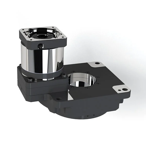

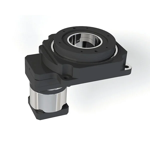
Hollow rotary platform uses a high-precision gear structure and radial bearings to improve torque and rigidity, enabling more stable load bearing. When paired with a servo motor or a stepper motor, it can perform arbitrary angle division. It not only meets the digit control that cannot be achieved by indexers, but also has a positioning accuracy comparable to that of direct drive motors, and can achieve the positioning of inertial loads within a short period of time.
Installation instructions for hollow rotary platform
 First, confirm whether the motor matches the platform and remove foreign matter on the surface. |
② Remove the flat-end screws on the transition flange and rotate the input end to adjust the position until the fastening bolts of the locking ring can be seen. |
③ Align the motor shaft with the reducer input end, insert it into the reducer, and pre-tighten the connecting bolts diagonally. |
 Tighten the locking ring and tighten the bolts; refer to the table below for torque. |
⑤ Use a torque wrench to tighten the fixing screws diagonally. Refer to the torque table below for the torque. |
⑥ Tighten the flat-end screw. |
Installation of the Shaft sleeve

Selection points of hollow rotary platform
Calculation of Load/Inertia of the Object to be Transported (Jw)
The inertia of the object to be transported should be less than 30 times that of the transmission device as a standard.
Output End
■ Calculation of Accelerating Torque (Ta)
Refer to the following formula:
Accelerating torque Ta [N·m] = (JM + JA + Jw) * π/30 * (N₂ - N₁)/t₁
where JM: Inertia of the motor [kg·m²]; JA: Inertia of the mechanism [kg·m²]; Jw: Inertia of the load [kg·m²]; N₂: Operating speed [r/min]; N₁: Starting speed [r/min]; t₁: Acceleration (deceleration) time [S].
■ Calculation of the Required Torque
The required torque is calculated by multiplying the sum of the load torque caused by friction impedance and the accelerating torque caused by inertia by a safety factor.
Required torque T = (Load torque [N·m] + Accelerating torque [N·m]) × Safety factor = (TL + Ta) × S. The safety factor S is greater than 1.5.
■ Selection of Motor
The required torque T of the motor must be within the specification range of speed-torque.
Speed-torque characteristic curve of the stepping motor.
Address
No. 148 Dongfeng Village, Xiaoshan District, Hangzhou City, Zhejiang Province, China
Tel


